Getting Started
After you’ve installed RPLCD, you need two more steps to get started: Correct wiring and importing the library.
Wiring
Via I²C
The wiring is much simpler if you have a LCD module with I²C support. These boards usually have a “backpack board” and look similar to this:
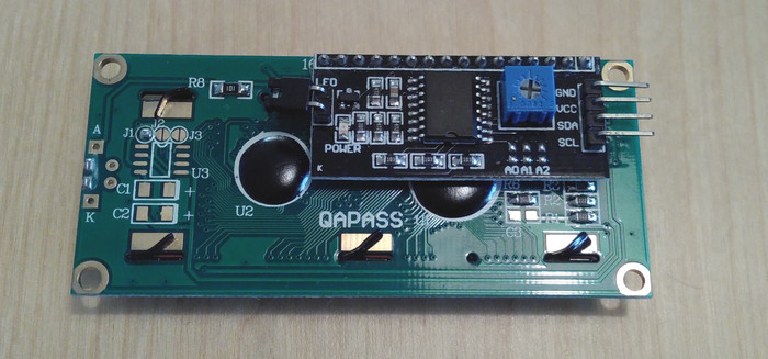
The board on this photo has a PCF8574 port expander chip on it. There are also boards with other chips, e.g. the Adafruit I²C/SPI LCD Backpack which uses an MCP23008 port expander.
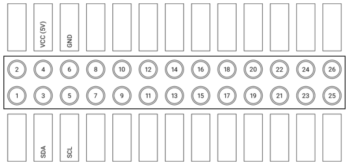
First, connect the pins on the right with the Raspberry Pi:
- GND: Pin 6 (GND)
- VCC: Pin 4 (5V)
- SDA: Pin 3 (SDA)
- SCL: Pin 5 (SCL)
To make things clearer, here’s a little visualization:
Via GPIO
If you don’t have an I²C version of the board, you can also connect the LCD Pins directly to the GPIO header of the Raspberry Pi.
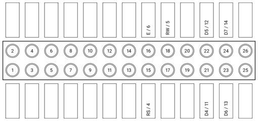
If you don’t know how to wire up the LCD to the Raspberry Pi, you could use this example wiring configuration in 4 bit mode (BOARD numbering scheme):
- RS: 15
- RW: 18
- E: 16
- Data 4-7: 21, 22, 23, 24
To make things clearer, here’s a little visualization:
After wiring up the data pins, you have to connect the voltage input for controller and backlight, and set up the contrast circuit. As there are some differences regarding the hardware between different modules, please refer to the Adafruit tutorial to learn how to wire up these circuits.
Via pigpio
If you decide to use the pigpio library to control the LCD, follow the
instructions set out above. Please keep in mind that the pigpio can only
use the BCM numbering scheme.
The advantage of using the pigpio library is that you could control the
backlight and contrast via PWM. You could also run the program on one computer
(there is no need for this computer to be a Raspberry Pi) and control a LCD on
any Raspberry Pi because pigpio follows a server-client approach. The
disadvantage is, that it might be a bit slower when updating compared to using
the GPIO library.
Initializing the LCD
Setup: I²C
First, import the RPLCD library from your Python script.
from RPLCD.i2c import CharLCD
Then create a new instance of the CharLCD class. For that,
you need to know the address of your LCD. You can find it on the command line
using the sudo i2cdetect 1 command (or sudo i2cdetect 0 on the original
Raspberry Pi). In my case the address of the display was 0x27. You also need
to provide the name of the I²C port expander that your board uses. It should be
written on the microchip that’s soldered on to your board. Supported port
expanders are the PCF8574, the MCP23008 and the MCP23017.
lcd = CharLCD('PCF8574', 0x27)
If you want to customize the way the LCD is instantiated (e.g. by changing the number of columns and rows on your display or the I²C port), you can change the corresponding parameters. Example:
lcd = CharLCD(i2c_expander='PCF8574', address=0x27, port=1,
              cols=20, rows=4, dotsize=8,
              charmap='A02',
              auto_linebreaks=True,
              backlight_enabled=True)
Setup: GPIO
First, import the RPLCD library from your Python script.
from RPLCD.gpio import CharLCD
Then create a new instance of the CharLCD class. If you
have a 20x4 LCD, you must at least specify the numbering mode and the pins you
used:
lcd = CharLCD(pin_rs=15, pin_rw=18, pin_e=16, pins_data=[21, 22, 23, 24],
              numbering_mode=GPIO.BOARD)
If you want to customize the way the LCD is instantiated (e.g. by changing the pin configuration or the number of columns and rows on your display), you can change the corresponding parameters. Here’s a full example:
from RPi import GPIO

lcd = CharLCD(pin_rs=15, pin_rw=18, pin_e=16, pins_data=[21, 22, 23, 24],
              numbering_mode=GPIO.BOARD,
              cols=20, rows=4, dotsize=8,
              charmap='A02',
              auto_linebreaks=True)
Setup: pigpio
First, import the the pigpio and RPLCD libraries from your Python script.
import pigpio
from RPLCD.pigpio import CharLCD
Then create a connection to the pigpio daemon
pi = pigpio.pi()
and create a new instance of the CharLCD class. If you
have a 20x4 LCD, you must at least specify the previously initiated pigpio
connection and the pins you used:
lcd = CharLCD(pi,
              pin_rs=15, pin_rw=18, pin_e=16, pins_data=[21, 22, 23, 24])
If you want to customize the way the LCD is instantiated (e.g. by changing the pin configuration or the number of columns and rows on your display), you can change the corresponding parameters. Here’s a full example:
import pigpio
from RPLCD.pigpio import CharLCD

pi = pigpio.pi()
lcd = CharLCD(pi,
              pin_rs=15, pin_rw=18, pin_e=16, pins_data=[21, 22, 23, 24],
              cols=20, rows=4, dotsize=8,
              charmap='A02',
              auto_linebreaks=True)
Writing Data
Now you can write a string to the LCD:
lcd.write_string('Hello world')
To clean the display, use the clear() method:
lcd.clear()
You can control line breaks with the newline (\n, moves down 1 line) and
carriage return (\r, moves to beginning of line) characters.
lcd.write_string('Hello\r\n World!')
And you can also set the cursor position directly:
lcd.cursor_pos = (2, 0)